Подробнее устранение неисправностей описано в руководстве по эксплуатации каждой модели.
На нашем сайте представлены запасные части для оборудования Carel.
Для подбора запасных частей Carel сообщите нам полную маркировку блока и наименование запчасти любым удобным способом.
Коды ошибок управляющих блоков для систем вентиляции и кондиционирования Carel (PCOxs электро)
| Код | Описание ошибки |
|---|---|
| E01 | Поступил сигнал от пожарной сигнализации |
| E02 | Неисправен датчик наружной температуры |
| E03 | Неисправен датчик температуры в помещении |
| E04 | Неисправен датчик температуры приточного воздуха |
| E05 | Неисправен датчик температуры возвращаемого теплоносителя |
| E08 | Неисправен датчик температуры возвращаемого теплоносителя после нагревателя второго нагрева |
| E09 | Неисправен датчик влажности приточного воздуха |
| E10 | Неисправен датчик влажности воздуха в помещении |
| E12 | Неисправен датчик температуры насыщения |
| E13 | Один или несколько аналоговых входов под ручным управлением |
| E14 | Один или несколько аналоговых выходов под ручным управлением |
| E15 | Один или несколько дискретных входов под ручным управлением |
| E16 | Один или несколько дискретных выходов под ручным управлением |
| E17 | Нет сигнала статуса от приточного вентилятора |
| E18 | Нет сигнала статуса от вытяжного вентилятора |
| E19 | Нет сигнала статуса от вытяжного и (или) приточного вентилятора |
| E20 | Низкая наружная температура для использования режима «лето» |
| E21 | Запуск заблокирован. Низкая температура возвращаемого теплоносителя или клапан в контуре нагревателя открыт менее чем на 80% (или иное значения согласно St13) |
| E22 | Защита от замерзания водяного нагревателя. Предварительная тревога |
| E23 | Защита от замерзания водяного нагревателя. Основная тревога |
| E24 | Неисправен насос в контуре водяного нагревателя |
| E25 | Защита от замерзания водяного нагревателя второго нагрева. Предварительная тревога |
| E26 | Защита от замерзания водяного нагревателя второго нагрева. Основная тревога |
| E27 | Неисправен насос в контуре водяного нагревателя 2 |
| E28 | Перегрев электронагревателя |
| E29 | Активировано оттаивание рекуператора |
| E30 | Неисправен привод ротора рекуператора |
| E31 | Неисправен компрессорно-конденсаторный агрегат (ККА) |
| E32 | Фильтр на притоке загрязнен |
| E33 | Фильтр на вытяжке загрязнен |
| E34 | Фильтр загрязнен |
| E37 | Отсутствует связь с платой расширения |
| E39 | Получен внешний сигнал тревоги |
| E40 | Перезапуск после подачи питания |
| E41 | Термозащита приточного вентилятора |
| E42 | Термозащита вытяжного вентилятора |
| E43 | Термозащита вентиляторов |
ENG
In addition, the HACCP alarm menu allows the following operations:
• delete an HACCP alarm by pressing Set & DOWN for 5 seconds when
displaying the list of alarms. This causes the HACCP to fl ash, the display
shows the message rES and the monitoring of HACCP alarms is
reinitialised;
• delete the entire memory of HACCP alarms, by pressing Set & UP &
DOWN for 5 seconds. This procedure displays the message rES, deletes
the entire memory of alarms and reinitialises the monitoring of the
HACCP alarms.
Display
Cause of the alarm
code
rE
Control probe fault
E1
Probe S1 fault
E2
Probe S2 fault
E3
Probe S3 fault
E4
Probe S4 fault
E5
Probe S5 fault
E6
Probe S6 fault
E7
Probe S7 fault
E8
Serial probe S8 not updated
E9
Serial probe S9 not updated
E10
Serial probe S10 not updated
E11
Serial probe S11 not updated
LO
Low temperature alarm
HI
High temperature alarm
LO2
Low temperature alarm
HI2
High temperature alarm
Immediate alarm from
IA
external contact
Delayed alarm from external
dA
contact
dor
Door open for too long alarm
Etc
Real time clock fault
LSH
Low superheat alarm
Low suction temperature
LSA
alarm
Maximum evaporation
MOP
pressure alarm
Low evaporation temperature
LOP
alarm
bLo
Valve blocked alarm
Communication error with
Edc
stepper driver
Stepper motor broken/not
EFS
connected
EE
Flash unit parameter error
EEPROM operating parameter
EF
error
HA
Type HA HACCP alarm
HF
Type HF HACCP alarm
Communication error with
MA
Master (only on Slave)
Communication error with
u1…u5
Slave (only on Master)
Alarm on unit 1 to 5 in the
n1…n5
network
Upload procedure with errors
up1…up5
on unit 1 to 5
Displayed probe wrong or
205
disconnected
MPXPRO — + 0300055EN rel. 1.0 30/08/10
Icon
Alarm
fl ash on
Buzzer
Reset
relay
display
ON
ON
automatic
OFF
OFF
automatic
OFF
OFF
automatic
OFF
OFF
automatic
OFF
OFF
automatic
OFF
OFF
automatic
OFF
OFF
automatic
OFF
OFF
automatic
OFF
OFF
automatic
OFF
OFF
automatic
OFF
OFF
automatic
OFF
OFF
automatic
ON
ON
automatic
ON
ON
automatic
ON
ON
automatic
ON
ON
automatic
ON
ON
automatic
ON
ON
automatic
ON
ON
automatic
OFF
OFF
automatic
OFF
OFF
automatic
automatic /
OFF
OFF
manual
OFF
OFF
automatic
OFF
OFF
automatic
manual/
OFF
OFF
disabled with
P14=0
ON
ON
automatic
ON
ON
automatic
OFF
OFF
automatic
OFF
OFF
automatic
OFF
OFF
manual
OFF
OFF
manual
ON
ON
automatic
ON
ON
automatic
ON
ON
automatic
OFF
OFF
—
OFF
OFF
—
Evaporator
Compressor
Defrost
fans
duty
unchanged
unchanged
setting(c4)
duty
unchanged
unchanged
setting(c4)
unchanged
unchanged
unchanged
unchanged
unchanged
unchanged
unchanged
unchanged
unchanged
unchanged
unchanged
unchanged
unchanged
unchanged
unchanged
unchanged
unchanged
unchanged
duty
unchanged
unchanged
setting(c4)
duty
unchanged
unchanged
setting(c4)
duty
unchanged
unchanged
setting(c4)
duty
unchanged
unchanged
setting(c4)
unchanged
unchanged
unchanged
unchanged
unchanged
unchanged
unchanged
unchanged
unchanged
unchanged
unchanged
unchanged
duty
unchanged
unchanged
setting(A6)
duty
setting(A6)
unchanged
unchanged
if A7≠0
unchanged
unchanged
unchanged
unchanged
unchanged
unchanged
OFF
unchanged
unchanged
OFF
(paragraph
unchanged
unchanged
6.10)
OFF
unchanged
unchanged
unchanged
unchanged
unchanged
unchanged
unchanged
unchanged
unchanged
unchanged
unchanged
unchanged
unchanged
unchanged
OFF
not performed
OFF
OFF
not performed
OFF
unchanged
unchanged
unchanged
unchanged
unchanged
unchanged
unchanged
unchanged
unchanged
unchanged
unchanged
unchanged
unchanged
unchanged
unchanged
unchanged
unchanged
unchanged
unchanged
unchanged
unchanged
64
Network
Continuous
Signalled on
solenoid
cycle
tLAN
valve
unchanged
√
—
unchanged
√
—
unchanged
√
—
unchanged
√
—
unchanged
√
—
unchanged
√
—
unchanged
√
—
unchanged
√
—
unchanged
√
—
unchanged
√
—
unchanged
√
—
unchanged
√
—
unchanged
√
—
unchanged
√
—
unchanged
√
—
unchanged
√
—
unchanged
√
—
unchanged
√
—
unchanged
√
—
unchanged
√
—
unchanged
√
√
unchanged
√
√
unchanged
√
√
unchanged
√
√
unchanged
√
—
unchanged
√
—
unchanged
√
—
not performed
√
—
not performed
√
—
unchanged
√
—
unchanged
√
—
unchanged
—
—
unchanged
—
—
unchanged
—
—
unchanged
—
—
unchanged
—
—
Tab. 9.b
-
Bookmarks
Quick Links
Updated:
17/03/2010
CAREL ir33
Q u i c k r e f e r e n c e H a n d b o o k
Ver. 1.1
Pag.1/12
Eng
Related Manuals for Carel ir33
Summary of Contents for Carel ir33
- Page 1
Updated: 17/03/2010 CAREL ir33 Q u i c k r e f e r e n c e H a n d b o o k Ver. 1.1 Pag.1/12… -
Page 2: Main Features Of The Instrument
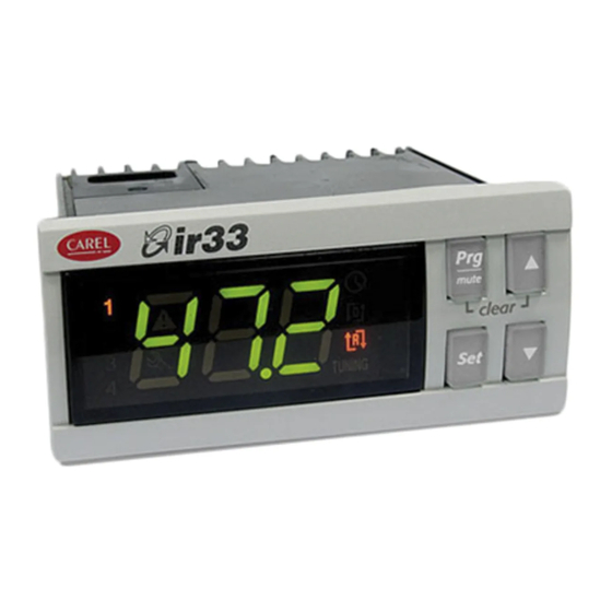
Updated: 17/03/2010 MAIN FEATURES OF THE INSTRUMENT USER INTERFACE ON/OFF switch button – UP button to increase temperature values DOWN button to decrease values — Activates/deactivates the manual defrost SET temperature button Prg/mute button Malfunctioning or failure warning icon High/Low temperature alarm icon icon is ON when defrost process starts icon is ON when compressor starts icon is ON when evaporator fans starts…
- Page 3
“0” that indicates the password prompt Press UP button to set the password – CAREL thermoregulators are provided with password set to 11 (the code of the password allows access to the configuration parameters) - Page 4
Updated: 17/03/2010 MANUAL Manual defrost is activated or deactivated if DEF/DOWN button is keep DEFROST pressed more than 5 seconds. When defrost starts display shows dFb (defrost begining) Defrost’s warning icon is ON when defrost is active Defrost can be interrupted simply by pressing again the DEF/DOWN button more than 5 seconds. - Page 5
Updated: 17/03/2010 HOW TO CHECK To check current temperature measured by a single installed probe, CAVITY PROBE proceeds as follow: TEMPERATURE 1. refers to the previous step how to get in the configuration parameter session — type C parameter 2. scroll the configuration parameter list, by using UP/DOWN buttons, until display shows the parameter /C1 (calibration or offset for cavity probe) 3. - Page 6
Updated: 17/03/2010 TABLE OF OPERATING PARAMETERS N° Code Range U.M. Description TEMPERATURE PROBE MANAGEMENT PARAMETERS 0…15 Measurement stability 0…15 Probe display response 0…100 Virtual probe Flag Selection °C or °F Flag Decimal point 1…6 Display on terminal 0…6 Display on external terminal 0…2 Type of probe 0…3… - Page 7
Updated: 17/03/2010 N° Code Range U.M. Description 0…1 Flag Enable autostart function in PD 0…1 Flag Select Pump down by time or pressure 0…250 Seconds Second compressor delay DEFROST MANAGEMENT PARAMETERS 0…4 Flag Type of defrost 0…250 Hours Interval between defrosts -50…200 °C/°F End defrost temperature, evaporator… - Page 8
Clean Alarm counter reset NOTE 1: Above operating parameters are available for all range of CAREL thermoregulators. Particularly all green highlighted parameters are available on new CAREL controller ir33 IRELF0HN245, currently installed on HD cabinets and counters NOTE 2: Blu highlighted operating parameters listed above are not influential for the functioning of the appliance. - Page 9
Updated: 17/03/2010 SERVICE ALLARMS AND SIGNALS SERVICE ALARMS SERVICE ALARMS DUE TO MALFUNCTIONING OR FAILURE PRODUCE A WARNING SIGNALS ON THE DISPLAY BY MEAN OF THE SERVICE ICON CAVITY PROBE In case of cavity probe faulty or malfunctioning display shows the error FAULT signal rE and E0 (cavity probe S1 fault) alternately The appliance works however and compressor starts are controlled by… - Page 10
Updated: 17/03/2010 TEMPERATURE ALARMS AND SIGNALS TEMPERATURE HIGH OR LOW TEMPERATURE ALARMS DUE TO MALFUNCTIONING OR ALARMS COMPONENTS FAILURE PRODUCE A WARNING SIGNALS ON THE DISPLAY BY MEAN OF THE ALARM ICON In case of low cavity temperature, referred to the cavity probe, the TEMPERATURE display shows a flashing error code LO. - Page 11
Updated: 17/03/2010 CONNECTIONS Follows all electrical connections available on ir33 CAREL controller , currently used in production IRELC0HN215 (646R05100) installed on STD BEN and CL freezer counter and STD BEN cabinet provided with internal light IRELF0EN215 (646R04700) installed on all STD BEN refrigerated counters, 400Lt refrigerated cabinets and all STD BEN cabinets without light Ver. - Page 12
Updated: 17/03/2010 IRELF0HN245 (646R09300) installed on HD counters and cabinets IRELF0EN225 installed on digital ROLL–IN IRELF0EHD15 installed on 400Lt FREEZER cabinet Ver. 1.1 Pag.12/12…
-
Bookmarks
Quick Links
Updated:
17/03/2010
CAREL ir33
Q u i c k r e f e r e n c e H a n d b o o k
Ver. 1.1
Pag.1/12
Eng
Related Manuals for Carel ir33
Summary of Contents for Carel ir33
- Page 1
Updated: 17/03/2010 CAREL ir33 Q u i c k r e f e r e n c e H a n d b o o k Ver. 1.1 Pag.1/12… -
Page 2: Main Features Of The Instrument
Updated: 17/03/2010 MAIN FEATURES OF THE INSTRUMENT USER INTERFACE ON/OFF switch button – UP button to increase temperature values DOWN button to decrease values — Activates/deactivates the manual defrost SET temperature button Prg/mute button Malfunctioning or failure warning icon High/Low temperature alarm icon icon is ON when defrost process starts icon is ON when compressor starts icon is ON when evaporator fans starts…
- Page 3
“0” that indicates the password prompt Press UP button to set the password – CAREL thermoregulators are provided with password set to 11 (the code of the password allows access to the configuration parameters) - Page 4
Updated: 17/03/2010 MANUAL Manual defrost is activated or deactivated if DEF/DOWN button is keep DEFROST pressed more than 5 seconds. When defrost starts display shows dFb (defrost begining) Defrost’s warning icon is ON when defrost is active Defrost can be interrupted simply by pressing again the DEF/DOWN button more than 5 seconds. - Page 5
Updated: 17/03/2010 HOW TO CHECK To check current temperature measured by a single installed probe, CAVITY PROBE proceeds as follow: TEMPERATURE 1. refers to the previous step how to get in the configuration parameter session — type C parameter 2. scroll the configuration parameter list, by using UP/DOWN buttons, until display shows the parameter /C1 (calibration or offset for cavity probe) 3. - Page 6
Updated: 17/03/2010 TABLE OF OPERATING PARAMETERS N° Code Range U.M. Description TEMPERATURE PROBE MANAGEMENT PARAMETERS 0…15 Measurement stability 0…15 Probe display response 0…100 Virtual probe Flag Selection °C or °F Flag Decimal point 1…6 Display on terminal 0…6 Display on external terminal 0…2 Type of probe 0…3… - Page 7
Updated: 17/03/2010 N° Code Range U.M. Description 0…1 Flag Enable autostart function in PD 0…1 Flag Select Pump down by time or pressure 0…250 Seconds Second compressor delay DEFROST MANAGEMENT PARAMETERS 0…4 Flag Type of defrost 0…250 Hours Interval between defrosts -50…200 °C/°F End defrost temperature, evaporator… - Page 8
Clean Alarm counter reset NOTE 1: Above operating parameters are available for all range of CAREL thermoregulators. Particularly all green highlighted parameters are available on new CAREL controller ir33 IRELF0HN245, currently installed on HD cabinets and counters NOTE 2: Blu highlighted operating parameters listed above are not influential for the functioning of the appliance. - Page 9
Updated: 17/03/2010 SERVICE ALLARMS AND SIGNALS SERVICE ALARMS SERVICE ALARMS DUE TO MALFUNCTIONING OR FAILURE PRODUCE A WARNING SIGNALS ON THE DISPLAY BY MEAN OF THE SERVICE ICON CAVITY PROBE In case of cavity probe faulty or malfunctioning display shows the error FAULT signal rE and E0 (cavity probe S1 fault) alternately The appliance works however and compressor starts are controlled by… - Page 10
Updated: 17/03/2010 TEMPERATURE ALARMS AND SIGNALS TEMPERATURE HIGH OR LOW TEMPERATURE ALARMS DUE TO MALFUNCTIONING OR ALARMS COMPONENTS FAILURE PRODUCE A WARNING SIGNALS ON THE DISPLAY BY MEAN OF THE ALARM ICON In case of low cavity temperature, referred to the cavity probe, the TEMPERATURE display shows a flashing error code LO. - Page 11
Updated: 17/03/2010 CONNECTIONS Follows all electrical connections available on ir33 CAREL controller , currently used in production IRELC0HN215 (646R05100) installed on STD BEN and CL freezer counter and STD BEN cabinet provided with internal light IRELF0EN215 (646R04700) installed on all STD BEN refrigerated counters, 400Lt refrigerated cabinets and all STD BEN cabinets without light Ver. - Page 12
Updated: 17/03/2010 IRELF0HN245 (646R09300) installed on HD counters and cabinets IRELF0EN225 installed on digital ROLL–IN IRELF0EHD15 installed on 400Lt FREEZER cabinet Ver. 1.1 Pag.12/12…